目录
- Chapter1: Computer Abstraction and Technology
- Chapter2: Instructions: Language of the Computer
- Chapter3: Arithmetic for Computers
- Chapter4: The Processor: Datapath and Control
- Chapter5: Large and Fast: Exploiting Memory Hierarchy
- Chapter 6: Parallel processor from client to Cloud (选讲,非考试内容)
- Appendix: Storage, Networks, and Other Peripherals (了解概念)
- 附录
Chapter 1
- 算法:影响IC,可能影响CPI
- 编程语言:影响IC和CPI
- 编译器:影响IC和CPI
- ISA:影响IC,CPI和
Execution Time
- Elapsed time: Total response time,determines system performance
- Processing , IO, OS overhead, idle time…
- CPU time: Time spent processing a given job
- different programs are affected differently by CPU & system performance
- Comprises user CPU time & system CPU time
- 提速:Clock Cycles和Clock Rate的trade off
- Elapsed time: Total response time,determines system performance
- 平均CPI由CPU硬件、指令类型等决定
Instruction Count由程序、指令集(ISA)和编译器决定
CMOS IC technology中
Pitfall
- Amdahl’s Law
- MIPS

Chapter 2
2 key principles
Instruction are represented as numbers.
Programs can be stored in memory to be read or written just like numbers.
Operations
指令的Format决定了指令的结构
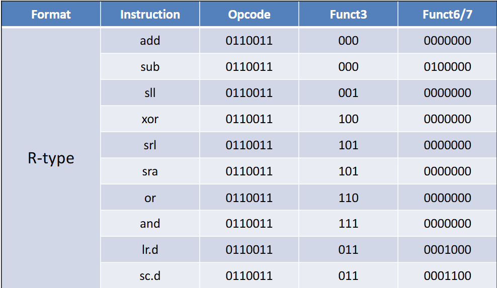
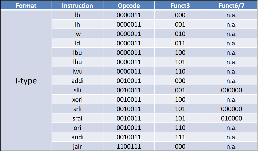
RISC-V指令集
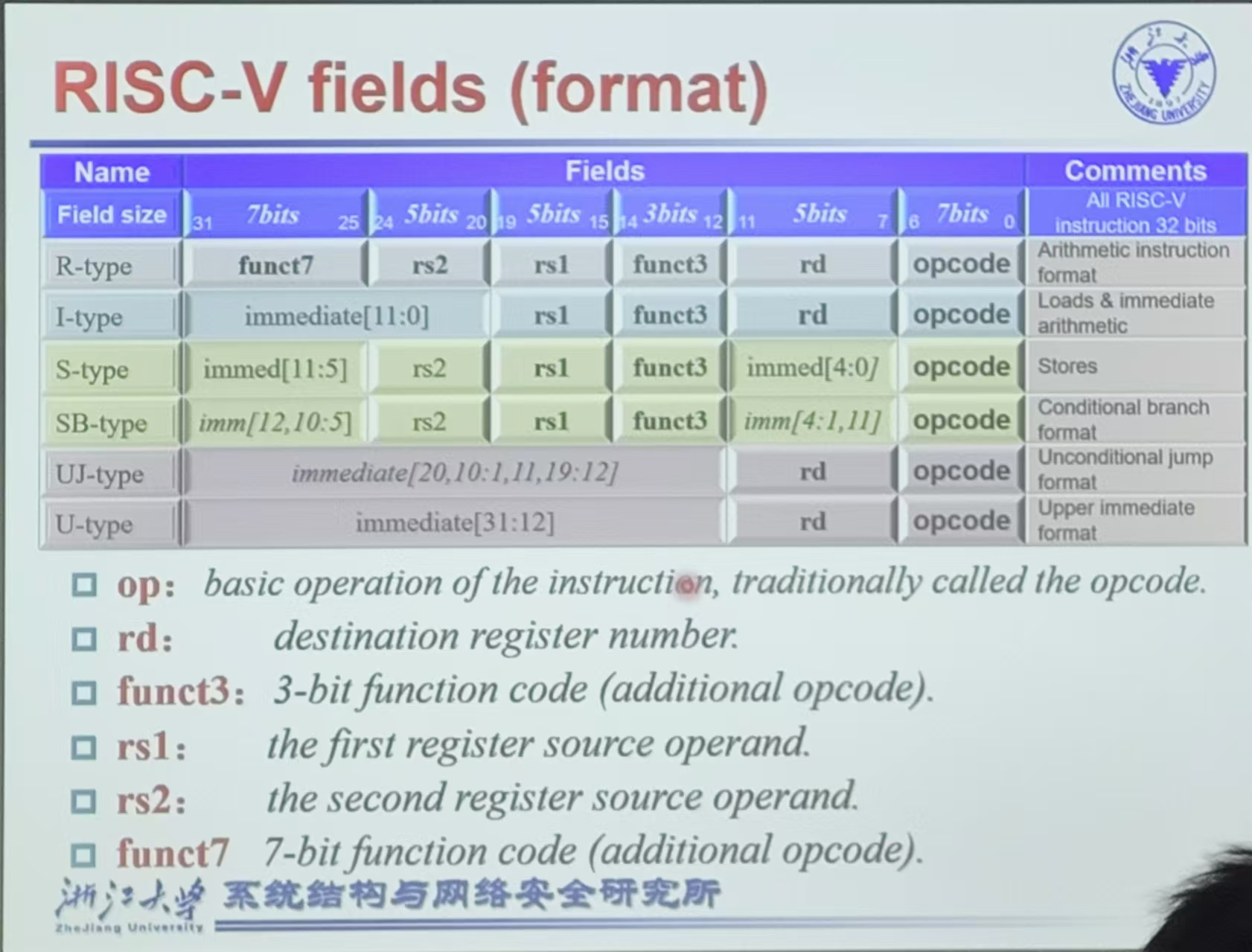
- R型:操作全寄存器
- I型:两个寄存器,一个立即数
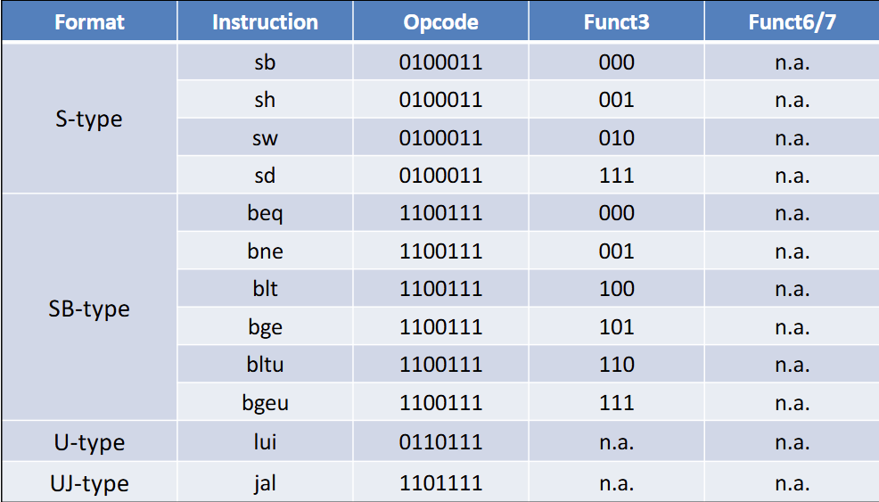
- S型:两个寄存器,一个立即数(被腰斩了)
- SB型:分支结构,与S型大体相似
- SB指令的imm[4:1,11]的安排是为了与S对齐
没有imm[0],很神奇吧,imm[12]是符号位拓展,默认第零位是0
- SB指令的imm[4:1,11]的安排是为了与S对齐
MIPS指令集
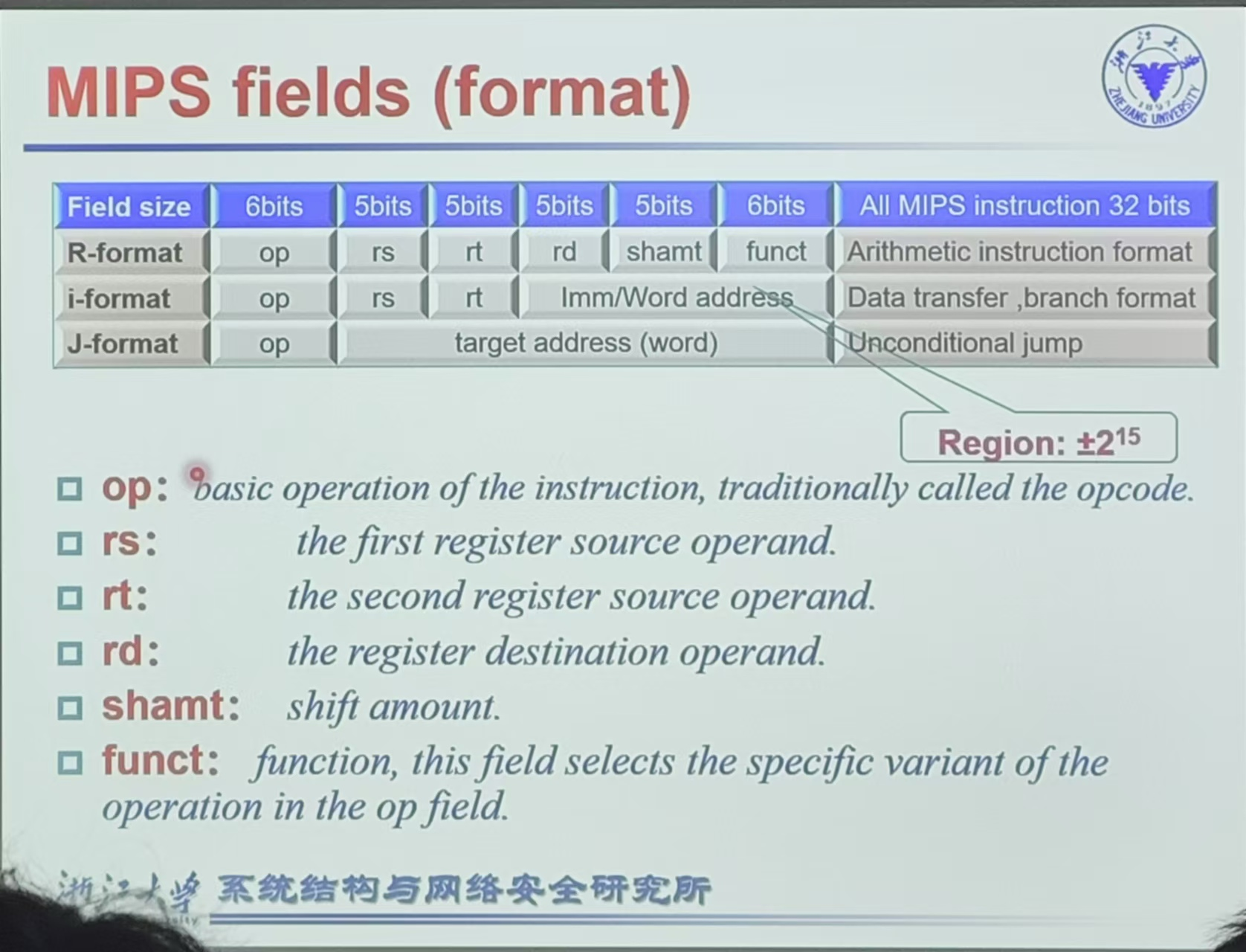
Arithmetic
One operation per instruction
3 variables(2 src+1 dest)
- add dest src1 src2 (dest = src1 + src2)
- sub dest src1 src2 (dest = src1-src2)
操作数得是寄存器
Risc-V有32个64位的寄存器(x0~x31)
- 32b word,64b doublewords
功能表见附录
Memory
只有读写两种操作
按byte操作
RISC-V是Little Endian(更低位的byte放在更小的地址)(Big Endian反之)
RISC-V不要求Memory Alignment
- 对齐:存储为0到3,4到7等,起始地址是4的倍数不会跨byte
示例:
A[12]=h+A[8],h在x21,A基址x22指令如下
ld x9, 64(x22) add x9, x21,x9 sd 72(x22), x9ld是load double word,64(x22)指A[8],即数字部分是相对基址的偏移量(以字节为单位)
示例:
h=h+55addi x9 x9 55Byte/Halfword/Word Operations
寄存器都是64位不变的,因而
- 在
lb,lh,lw指令时用符号位扩展 - 在
lbu,lhu,lwu指令时用0扩展
- 在
Logical Operations
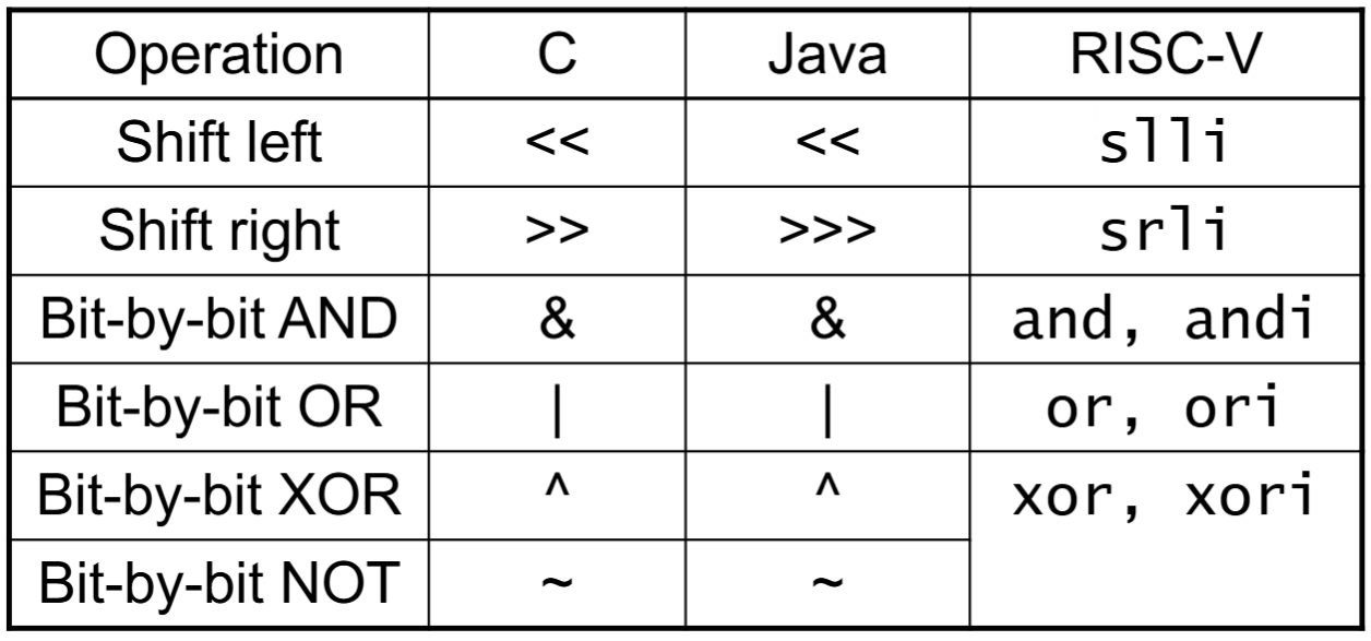
按位取反是不需要的(与全一取异或)
- Shift Operations : I format
- AND Operations & OR Operations & XOR Operations: R format
beq : 相等则执行;bne : 不等则执行
beq x21,x22,L1,其中L1指代一个指令,值为那条指令与本指令的相对位置。slt : 以
slt x5, x19, x20为例,若 则 为1blt : 若 则跳转;bge : 若 则跳转
- 以及相应的unsigned形式bltu,bgeu
SB指令的立即数处理
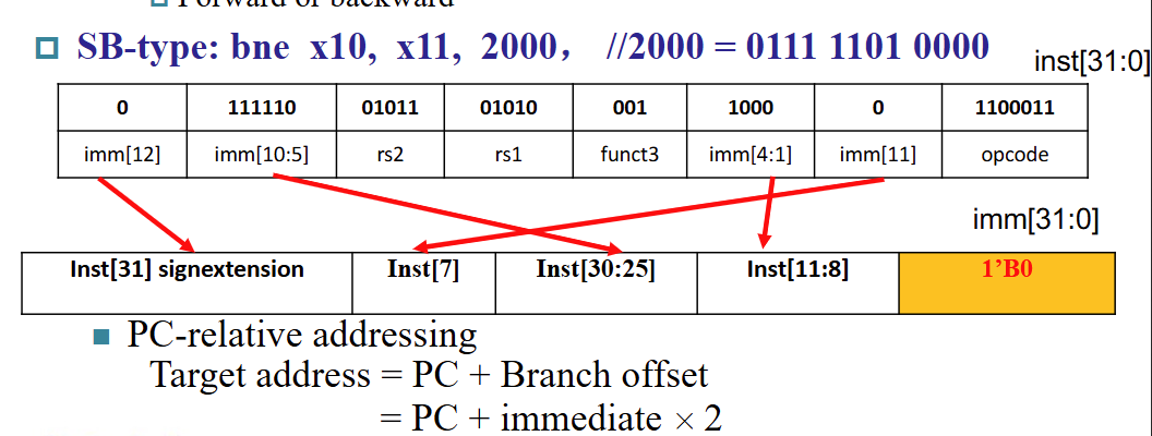
会省略掉最低位的零,因而需要以half word对齐(实际设计是word对齐)
循环的写法
- g ~ k对应x20 ~ x24, base A[i] 存在 x25
    do{
    	g = g + A[i];
    	i = i + j;
    }while(i!=h);
LOOP: slli x10,x22,3 #按字节数A[i]相对于A的偏移量 add x10,x10,x25 #x10存储A[i]的地址 ld x19 ,0(x10) #x19存储A[i]的值 add x20 x20 x19 add x22,x22,x23 bne x22,x21,LOOPwhile(A[i] == k) i+=1;LOOP: slli x10,x22,3 add x10,x10,x25 ld x9,0(x10) bne x9,x24,EXIT addi x22,x22,1 beq x0,x0,LOOP EXIT:....
Q:LOOP的值为多少? A:相对调用语句 beq x0,x0,LOOP 的偏移量,即 -5*4=-20
使用jalr实现Switch
switch ( k )  {
	case  0 :    f  =  i+  j ;  break ;    /*  k  =  0  */
	case  1 :    f  =  g +  h ;  break ;   /*  k  =  1  */
	case  2 :    f  =  g  -h ;  break ;   /*  k  =  2  */
	case  3 :    f  =  i-j ;  break ;    /*  k  =  3  */
}
使用 jump address table 解决
假设 f ~ k 对应 x20 ~ x25, x6 存储 jump address table 的基址,则对应汇编代码如下
blt x25, x0, Exit      # test if  k  <  0
bge x25, x5, Exit      # if  k  >=  4,  go to Exit
slli x7, x25, 3        # temp reg x7  =  8  *  k  (0<=k<=3)
add x7, x7, x6         # x7  =  address of JumpTable[k]
ld x7, 0(x7)           # temp reg x7 getsJumpTable[k]
jalr x1, 0(x7)         # jump based on register x7(entrance)
Exit:...
...
L0:add $s0, $s3, $s4   # k  =  0  so  f  gets  i+j
   jalr x0, 0(x1)      # end of this case so go to Exit
L1:add $s0, $s1, $s2   # k  =  1  so  f  gets  g+h
   jalr x0, 0(x1)      # end of this case so go to Exit
L2:sub $s0, $s1, $s2   # k  =  2  so  f  gets  g-h
   jalr x0, 0(x1)      # end of this case so go to Exit
L3:sub $s0, $s3, $s4   # k  =  3  so  f  gets  i-j
   jalr x0, 0(x1)      # end of  switch statement
代码理解:
为什么
slli x7, x25, 3?A:每条指令都是4B的,下面每个case带2条指令,因此乘以8
每个case的最后一句的
jalr x0, 0(x1)是什么作用?A:跳转回 x1 指令(即Exit),下一条指令没有必要存下来
代码中出现的
$s0,$s3,$s4都是什么东西?A:这是寄存器的别名
ld x7 0(x7)是为什么?A:类似于C语言中解引用的过程,可以这么理解。如L0这种label存储的是指令单位置(是一个指向指令的指针),而x6存储的是L0的地址(也就是x6是一个二级指针),因此通过
x7=x6+8*k得到的是存储Lk的地址的寄存器的地址,则此处 ld 指令过后就得到了 Lk的地址
Basic Blocks
- 要求:
- 没有分支
- 不会有跳转到中间的情况 (“No branch targets/branch labels, except at beginning”)
- 编译器会对 basic blocks 进行加速
- 要求:
Supporting Procedures
函数调用的6个步骤
- Place Parameters in a place where the procedure can access them
- Transfer control to the procedure:jump to
- Acquire the storage resources needed for the procedure
- Perform the desired task Place the result value in a place where the calling program can access it
- Return control to the point of origin
Procedure Call Instructions
- jal jalr : 无条件跳转 (作caller使用)
- Jump-and-link :
jal x1,ProcedureAddress[UJ型]将紧随其后的下一条指令存入 x1 (如果是 x0 就与 goto 指令等价)
并跳转至
ProcedureAddressUJ 指令的立即数处理
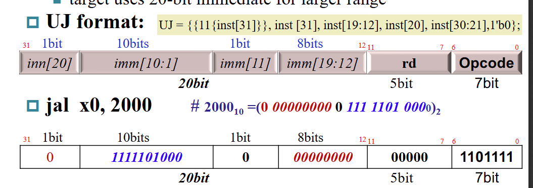
- 可以做到约 1MB 的跳转范围
- 因为省略最低位同样需要 half word 对齐
- Jump-and-link-register :
jalr x0,0(x1)[I型] (作callee使用)- 跳转到
0(x1)的位置 - 下一条指令存入 x0 (丢掉不要)
- 因为寄存器的引入可以实现更大的跳转范围
- 可以用作switch功能(实例见Conditional Operations部分)
- 跳转到
- Jump-and-link :
- jal jalr : 无条件跳转 (作caller使用)
参数的功用
- a0 ~ a7(x10 ~ x17) : 传参
- ra/x1 : 传返回地址
堆栈
栈:高地址到低地址
堆:低地址到高地址
包括3个参数: push, pop, 堆栈指针(sp)
sp存在两种用法:指向最后一个和指向空的,本课程使用指向最后一个的用法。
以栈为例:
push:
addi sp, sp, -8
sd ..., 0(sp)
pop:
ld ..., 0(sp)
addi sp, sp, 8
为了减少入栈出栈,对寄存器进行分类
- t0 ~ t2(x5 ~ x7) 是临时寄存器,函数调用不保存值
- a0 ~a7 用于传参
样例:阶乘求解
int fact ( int n ){
    if ( n  <  1 )   return  ( 1 ) ;
    else return   ( n  *  fact ( n  -1 ) ) ;
}
fact: addi sp, sp, -16 # adjust stack for 2 items sd ra, 8(sp) # save the return address:x1 sd a0, 0($sp) # save the argument n:x10(a0) addi t0, a0, -1 # x5 = n - 1 bge t0, zero, L1 # if n >= 1, go to L1(else) addi a0, zero, 1 # return 1 if n <1 addi sp, sp, 16 # Recover sp(Why not recover x1 and x10 ?) jalr zero, 0(ra) # return to caller L1: addi a0, a0, -1 # n >= 1: argument gets ( n -1 ) jal ra, fact # call fact with ( n -1) add t1, a0, zero # move result of fact(n -1) to x6(t1) ld a0, 0(sp) # return from jal: restore argument n ld ra, 8(sp) # restore the return address add sp, sp, 16 # adjust stack pointer to pop 2 items mul a0, a0, t1 # return n*fact ( n -1 ) jalr zero, 0(ra) # return to the caller
代码理解:
ra是干什么的?
书上说法是”保存函数调用返回地址“,这里可以举例子帮助理解。
在这段代码中,修改ra的地方除了ld只有jal,前者没啥分析价值,只看
jal ra, fact那句。此处会将jal的后一条指令存入ra,也就是说如果运行了这句话,跳转到fact标签运行,一通操作完之后(肯定入栈和弹栈数量持平),运行jalr zero,0(ra)就会跳回到jal的下一句,即从add t1, a0, zero开始跑。如果放到c里面理解(其实高级语言没有对应的东西),相当于在调用函数之前标记了一下函数后面那句话说是在这里断开开始递归的所以要从这里接着跑。
怎么理解a0的双重身份?
a0在传入参数的时候代表 ,计算完成的时候才作为 存在。例如考虑L1的部分。
addi a0, a0, -1是 njal ra, fact和add t1, a0, zero处因为递归调用的完成是存储的 于是很快就用 t1这个临时变量存起来了ld a0, 0(sp)恢复 a0 为mul a0, a0, t1jalr zero, 0(ra)的位置 a0 终于成为计算结果addi sp, sp, 16 # Recover sp(Why not recover x1 and x10 ?)已经到最底层了,a0不需要往下传,下次使用就是作为 所以不用改; ra没有变化也不用改
Memory Layout
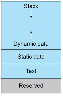
Dynamic data : 堆栈,配有 sp
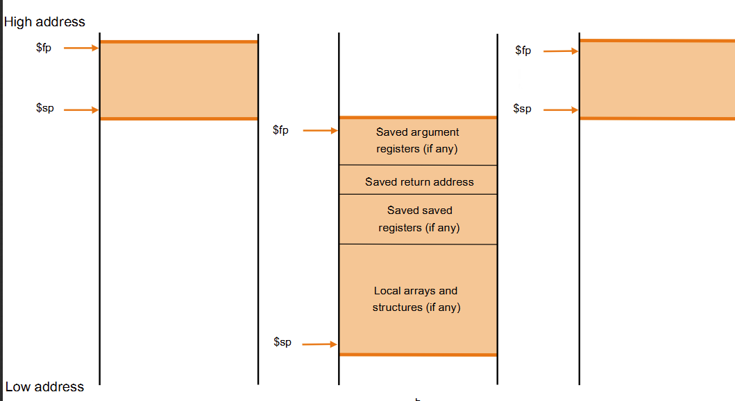
- fp(frame pointer) :指向当前函数压进去的第一个参数的位置(当前进程的起始位置)
- save saved registers : 超过现有32个的寄存器使用(类似于c的malloc)
static data : 静态变量(如数组,字符串)、x3 (global pointer)
text : 代码
Character Data
- Byte-encoded character sets
- ASCII : 128 个字符,其中 33 个是控制字符
- Latin-1 : 在ASCII基础上加了96个可显示字符
- Unicode : 32b
- UTF-8 , UTF 16:可变长度的编码
RISC-V Addressing for 32b Immediate and Address
- U type指令有20位立即数,效果如下

则如果要 load 一个 32b 的数可以这样做
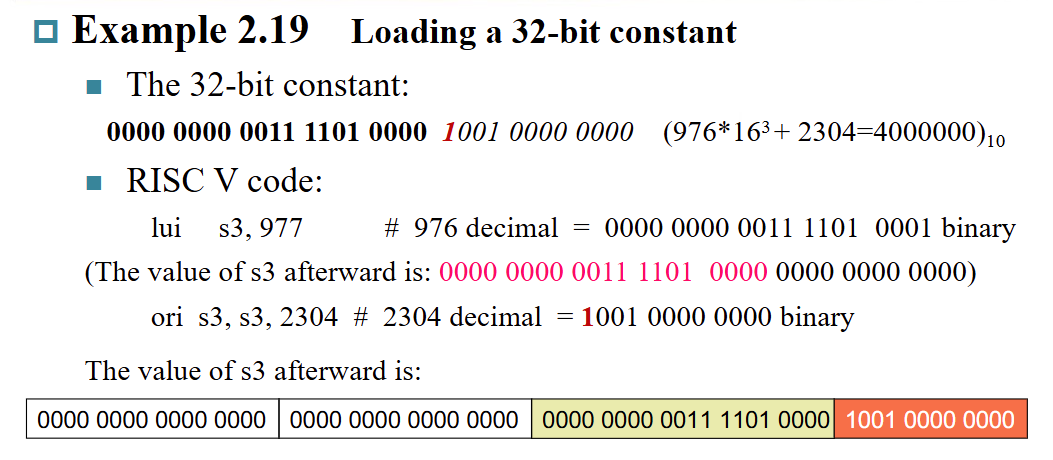
Q:为什么是 977 而非 976?
A: 2304的符号位是1,赋值的时候符号位扩展需要补一个1消除掉(也就是值+低一位的值)
Synchronization
- Load reserved:
lr.d rd,(rs1)- 从 rs1 读到 rd
- 内存预留
- Store conditional:
sc.d rd,(rs1),rs2- 从 rs2 存到 rs1里面的地址
- 如果该地址未被占用就返回0,反之返回非零值(且不修改)
Other RISC-V Instructions
- RV64I & RV32I : 64/32b寄存器
- RV64I中的 addw, subw, addiw, sllw,…是专门处理32b的
- RV32I和RV64I加上后缀表示更多的功能
- M:支持整数乘除法
- A:支持原子操作
- F:支持单精度浮点数
- D:支持双精度浮点数
- C:支持压缩指令(有16b指令)
Chapter 3
默认64bit为double word,一个word为32bit
补码可以直接加减,不可直接相乘!
- (?)如(1001)2平方不会得到49,但是如果补全成(11111001)2的平方可以
浮点数:Single precicion ~ Quadruple precision
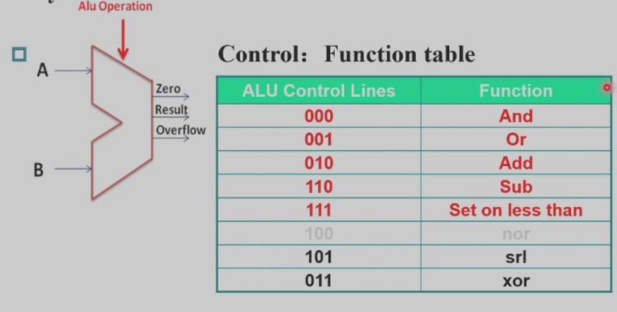
ALU
加减法溢出条件

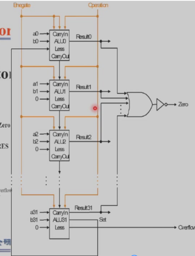
注:上图的set传到less是为了执行slt操作
超前进位加法器
一位版本
(generate)
(propogation)
则,
四位版本
对每个 进行展开,得到结果如下
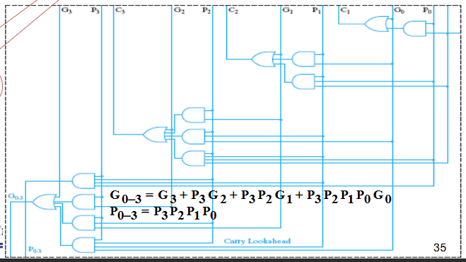
- 到 同步可得
十六位版本
- fan-in限制不能继续展开了
乘法
符号问题:一般转成绝对值运算再回去
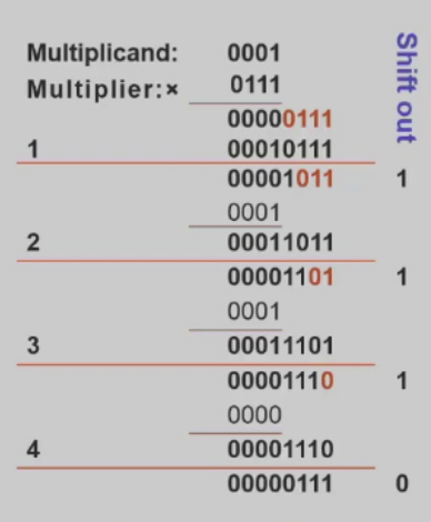
实操:龟速乘做法 “山不就我我来就山” 运算结果右移,被乘数不动
乘数和结果右移同步,可以利用低位存储乘数
- [了解] Booth’s Algorithm
Idea: 1111010-> 10000000 + 10 -1000
除法
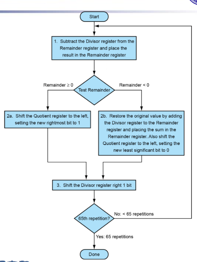
- 长除法的减法版本
- 允许有试减环节,不判断先减再说
- 具体操作(V1):除数存在寄存器左边,逐渐右移试减;被除数(余数)放在寄存器右边不用动
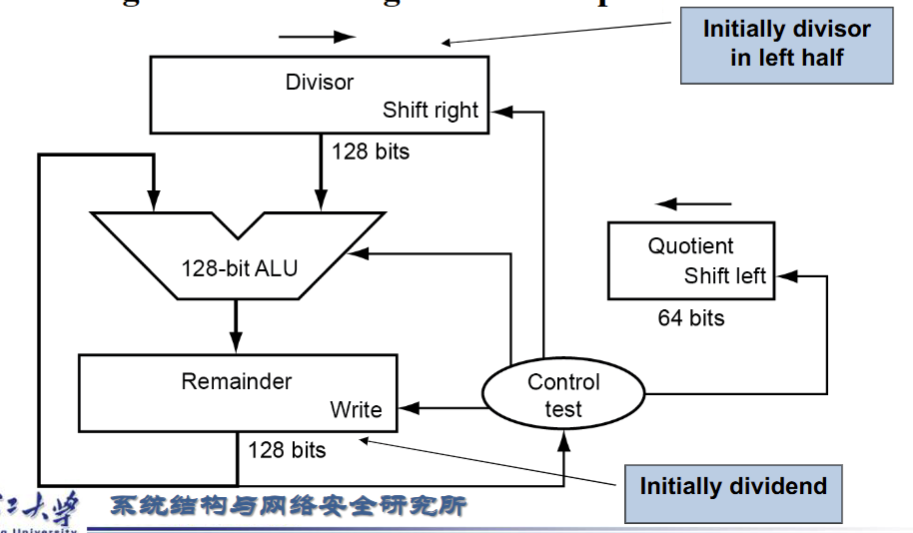
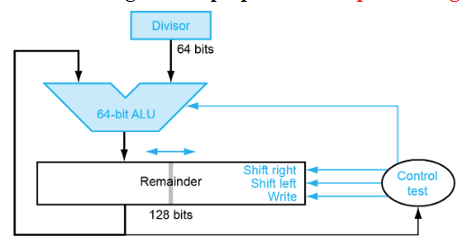
- V2(优化了存储空间):除数不用开二倍长度,Remainder寄存器将被除数放在右侧,逐步左移,Divisior对齐Remainder最左侧进行减法操作。减法结果从右侧存入Remainder充当V1的Quotient
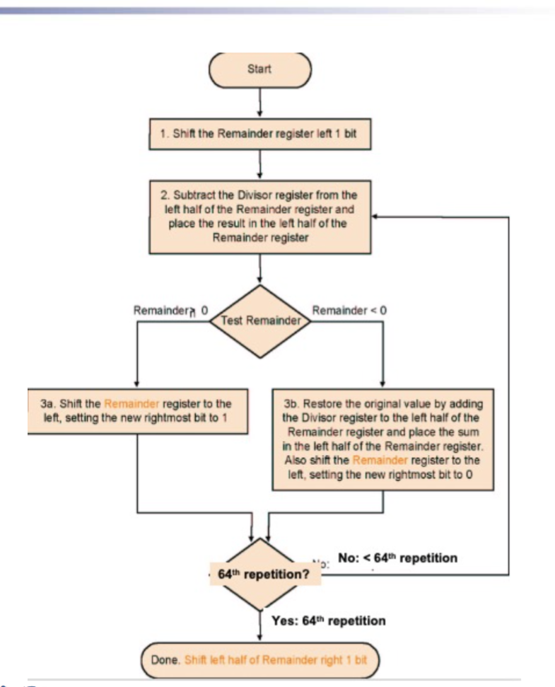
- 因为第一次减法结果必定为0,所以先左移再做减法。随之导致最后多移一次,故加上了ShiftRight接口
Q:负数除法,余数和商的符号问题?
A
- 除法无法并行实现:依赖前一次的结果
- [可以了解]Faster dividers(e.g. SRT division)
- Risc-V中的除法指令
- div,rem:有符号除法
- divu,remu:无符号除法
- 处理器不会对除0和溢出的情况进行报错,需要自行处理
浮点数
仿照科学计数法,可以将浮点数记为 。
- 上溢:正指数太大
- 下溢:负指数太小
表示形式
RISC-V
- float : 1位符号位+8位指数+23位尾数
- double : 1位符号位+11位指数+52位尾数
IEEE 754浮点数标准:将尾数的1隐含掉(类似科学计数法没有前导零,尾数的第一位必然为1),但0是例外,其表示为 。例如一个浮点数尾数部分表示为 ,则其值实际为 。
- 对异常值有特殊的表示

- 整个浮点数不是补码表示法而是符号-数值形式,但指数部分使用补码表示
- 移码表示法 :对指数部分加上一个偏移量以方便比较大小(类似从有符号整数到无符号整数范围的位移),IEEE 754规定 float 偏移量127, double 偏移量1023。则一个浮点数实际值为 有效位数 。
- 所以float绝对值最小的是 ,最大的Fraction:111111,约为2.0,绝对值最大的就是 。双精度分别为 和
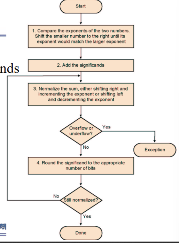
加减
- 对齐:指数小往指数大对齐
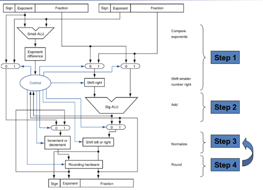
乘除
- 指数相加(但是要把bias补回来)
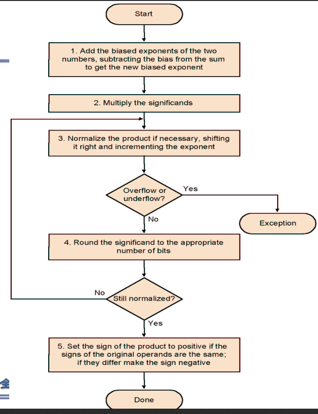
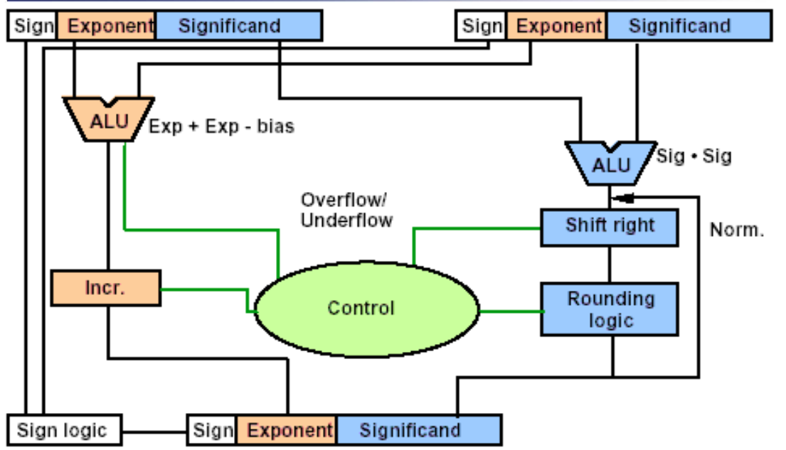
(除法类似)
Accurate Arithmetic
- 三个extra bits(不一定系统有)
- guard:
- round:
- sticky:
- TODO:理解三个extra bits的作用并了解其在浮点数运算具体操作
Chapter 4
单周期CPU
Implementation Overview
1st: identical
- 从内存中取出指令
- 解码,(读寄存器)
2nd:依据指令类型,进行内存访问/计算/分支
- ALU计算
- 访问内存,读写
- 修改PC
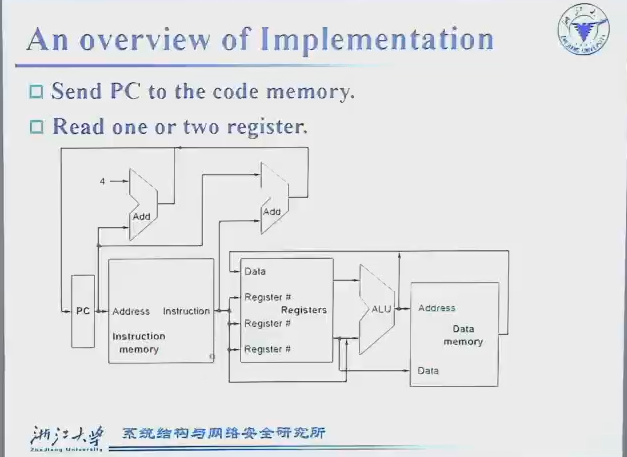
PC:寄存器,电脑运行指令的指针
Instruction Memory:存储指令,用来读取
Registers:寄存器读出/写入
Data Memory:更大的内存
ALUs
- 右下:用于寄存器加减等操作
- 左上:正常运行,
pc=pc+4 - 右上:非正常运行(如jal),偏移值来自指令
多处数据汇流:需要mux
- 下:ALU操作数可能是与立即数或者寄存器;寄存器出来的值(还没懂,待研究!!!)
- 中:指令可能只是算数运算,结果从ALU产生,也可能是如
ld t1, 0(t2)之类从 Data Memory产出 - 上:是否跳转决定PC的改变量
图上是数据流向的示意图datapath,但读还是写之类需要另外一套控制系统,如下图蓝色部分
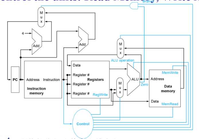
Datapath
部件
组合逻辑:ALU、Adder、Multiplexer
时序逻辑:Registers、Register files、存储器
Registers
- 写使能 Write Enable : 置为1且有效时钟边沿到来时修改数据输出为输入值
Register files:32个Register
- 32位输出端口 busA busB & 32位输入端口 busW
- 5位输入端口 RW RA RB
- Clk & Write Enable
- 读操作:RA 作为地址选择的数据输出到 busA ; RB busB,不受 clk 限制
- 写操作:当 Write Enable 为1时 RW 作为地址选择的寄存器写入 busW 的数据,受 clk 限制
存储器:对应示意图中 Data Memory 的部分
- 输入输出端口 DataIn & DataOut
- 地址线 Address
- Clk & Write Enable
- 读操作: Address 处数据输出到 DataOut
- 写操作:当Write Enable为1且时钟边缘有效时向 Address 处写 DataIn
Summary:三个部件在读功能时不受 clk 限制,相当于组合逻辑部件,但写操作都要在 clk 有效边缘
Q :非阻塞和阻塞赋值?
A :非阻塞等式右边的值统一评估完一起赋值;阻塞赋值是逐条进行,以这组代码为例
always @ (posedge clk)begin
	c<=1;
	b<=c;
	a<=b;
end
上文是非阻塞赋值,因而c = 1需要两个时钟才能给到a
always @ (posedge clk)begin
	c=1;
	b=c;
	a=b;
end
这是阻塞赋值,运行是逐行的,因此在一个周期内就能完成 a=b=c=1 的任务
各类操作对应的 Data path 和 Control 情况
完整结构图
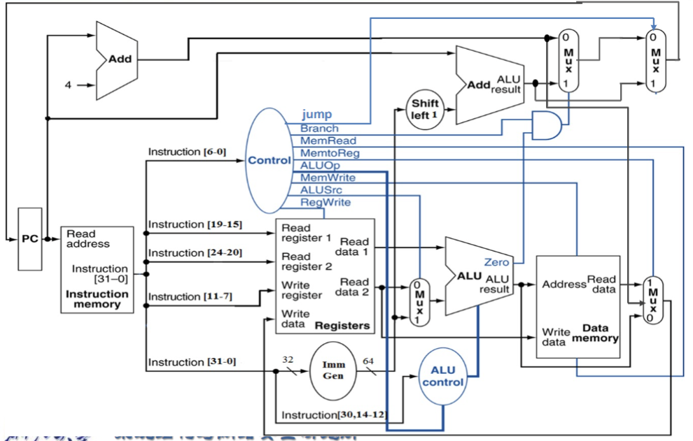
Control信号的作用
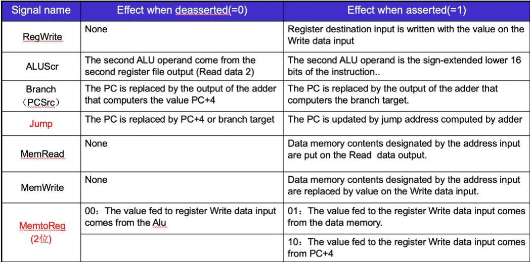
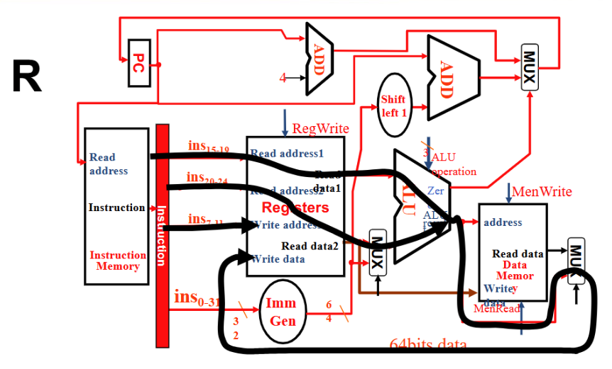
R型
- Instruction 流向 Reg1 和 Reg2 和 Wreg , Reg1 与 Reg2 进入 ALU ,ALU result 直接从 Mux 流向 Reg 的 Write Data
- RegWrite 1, ALUSrc 0, ALU operation 取决于具体指令, MemWrite 和 MemRead 0,MemtoReg 00, PCSrc 0
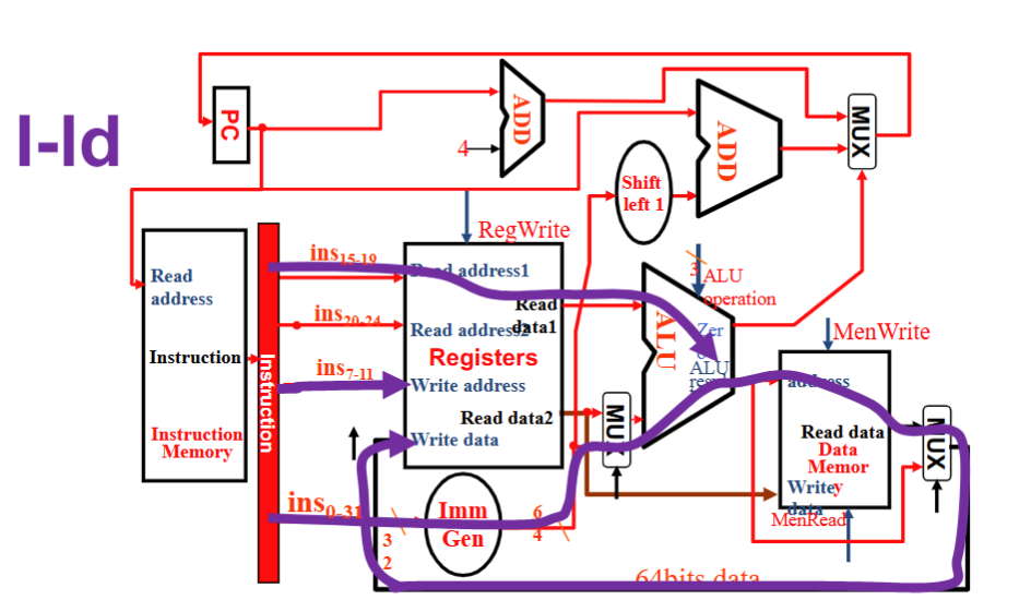
I 型
- Instruction 流向 Reg1 和 WReg 及 Imm Gen , Imm Gen 和 Reg1 进入 ALU ,结果输入 Memory address , 再从 MUX 流回 Reg Write Data.
- RegWrite 1, ALUSrc 1, ALU operation加, MemWrite 0, MemRead 1, MemtoReg 01, PCSrc 0
S 型
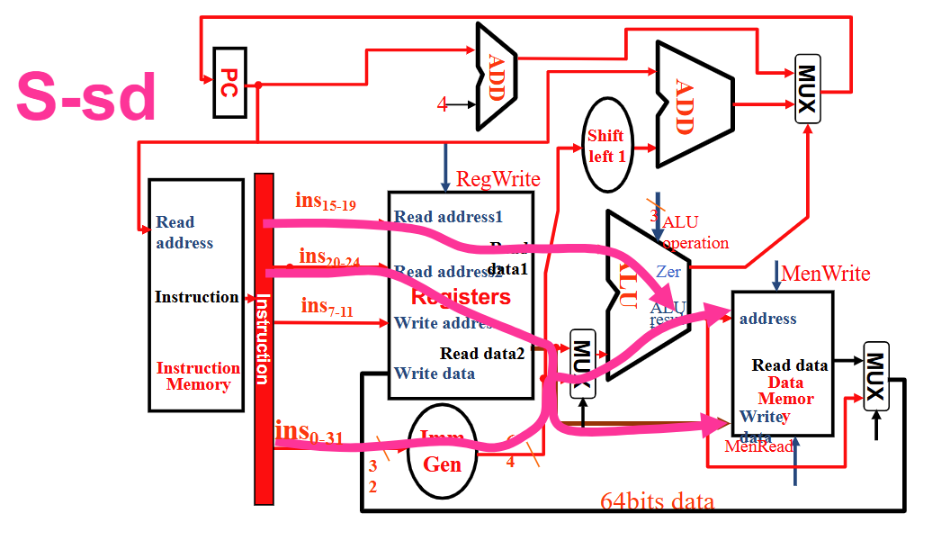
- Instruction 流向 Reg1, Reg2 和 Imm Gen, Imm Gen 和 Reg1 进入 ALU,结果输入 Memory address, Reg2 流向 Memory Write Data
- RegWrite 0, ALUSrc 1, ALU operation加, MemWrite 1, MemRead 0, MemtoReg 无所谓 , PCSrc 0
SB 型
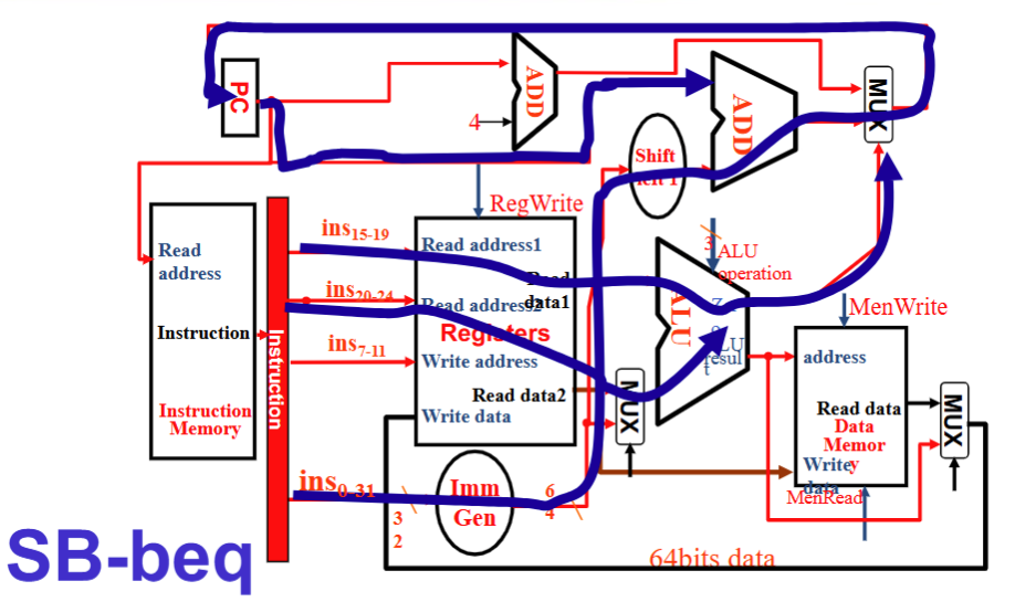
- Instruction 流向 Reg1, Reg2 和 Imm Gen,Reg1 和 Reg2 流入 ALU , ALU 的zero 流向顶上的 MUX, Imm Gen 流向 PC 的一个加法器
- RegWrite 0, ALUSrc 0, ALU operation减, MemWrite 0, MemRead 0, MemtoReg 无所谓, PCSrc 由 ALU 的 zero 给出
J 型
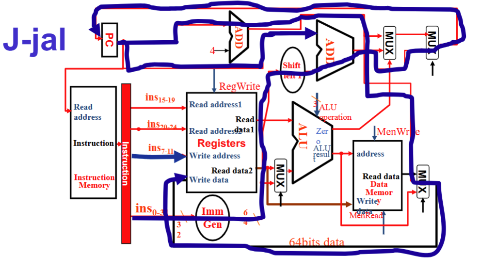
- Instruction 流向 Imm Gen 和 WReg , Imm Gen 流向 Shift left1 从而进入PC的加法器, PC+4 汇入 Data Memory 右边的 MUX 再到 Reg Write Data
- RegWrite 1, ALUSrc 无所谓, ALU operation 无所谓, MemWrite 0, MemRead 0, MemtoReg 10 , PCSrc 1
汇总:Control信号
main control

ALU control

Pipeline
理论基础
Five stages
- IF : Instruction fetch from memory
- ID : Instruction decode & register read (同时进行)
- EX : Execute operation or calculate address
- MEM : Access memory operand
- WB : Write result back to register
不是所有指令都五步齐全,但是那一步还是要走
流水线处理 CPI=1
存在问题
数据竞争:相邻两指令用到同寄存器,存在依赖关系
插入 stall
- 需要对一段有依赖关系的代码算总时钟周期,能把依赖关系消除掉
旁路(bypass)过来(算完了马上取出来用,不走流程)
控制竞争:比如前一条指令是跳转,那么后一条指令执行什么取决于前一条的结果
Branch Prediction
预测是否跳转(基于普遍历史经验预测),预测错误再插入stall
实现
Datapath
- 每层之间加寄存器,把结果存下来以为下一条指令做缓冲
- 以ld指令为例:直接使用上述设计最后写回的地址出问题了 Write address(后面要用到的一切信号) 跟着逐级移动(不能直接跳层否则流程出问题)
Control
- IF/ID解码指令,同单周期
- 后面边传边用边丢
Hazard
Data Hazards
- Detect

注意若 Rd 是 x0 就没必要了
若前一条指令是 ld 则无法旁路处理
ID/EX.MemRead and
((ID/EX.RegisterRd= IF/ID.RegisterRs1) or (ID/EX.RegisterRd=IF/ID.RegisterRs2))
Solve
bypath
一般可以从EX/MEM,MEM/WB旁路到ID/EX,因此需要设置一个选择器控制从哪里旁路(处理 Double Data Hazard)
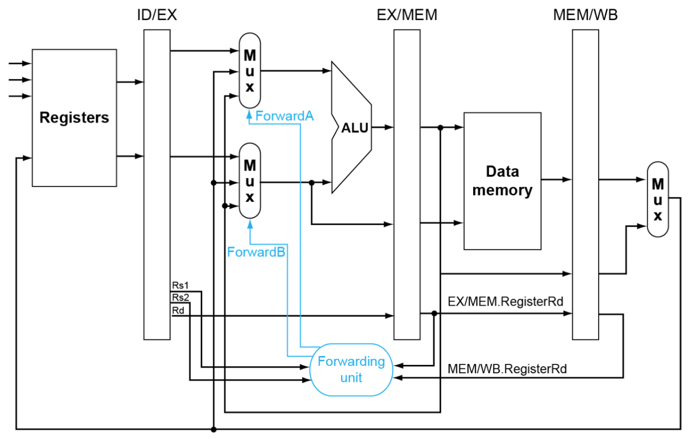
其中FowardA的信号对应选择方式如下,FowardB同理
if (MEM/WB.RegWrite and (MEM/WB.RegisterRd≠ 0)
	and not(EX/MEM.RegWrite and (EX/MEM.RegisterRd≠ 0)
			and (EX/MEM.RegisterRd=ID/EX.RegisterRs1))
			and (MEM/WB.RegisterRd= ID/EX.RegisterRs1)) ForwardA= 01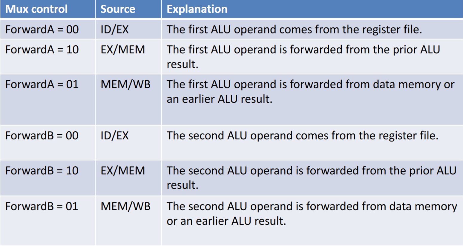
bubble
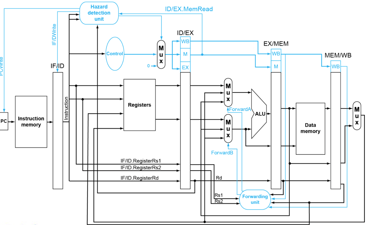
- 前一条指令是
ld,无法直接旁路,插入一个 bubble 可以从 MEM 旁路到 EX(Load-Use Hazard) - 强制清空 EX 到 WB 的所有 ( do nop )
- 只需要:控制信号置零(新增一个 Mux 用于控制)
- 阻止 PC 和 IF/ID 的更新(新增 Hazard detection unit 用于处理)
- 前一条指令是
Branch Hazards
使用 Predictor 预测行为
- 1b :与上次跳转结果相同,索引与该指令PC相同
- 缺点:在双重循环的内层跳出循环和重进循环时会错两次
- 2b :增加一次的容错
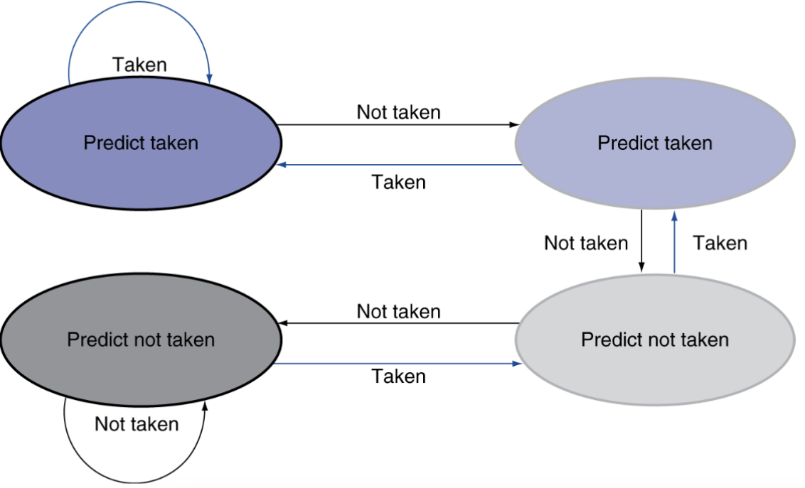
但是计算 PC 仍然会浪费一个周期
- 预存储好 PC 跳转的值
- 缺点:空间不够啊
- sol :存最近的
- 缺点:空间不够啊
Instruction-Level Parallelism(ILP)
- Multiple issue (多发)
CPI<1 ,所以改用 IPC 衡量效率
指令的依赖关系会使得实际 IPC 小于理论
Static Multiple issue
例如:每次同时处理一个ALU/branch+一个load/store指令
- 需要额外的寄存器,额外的ALU(只用加法就行)
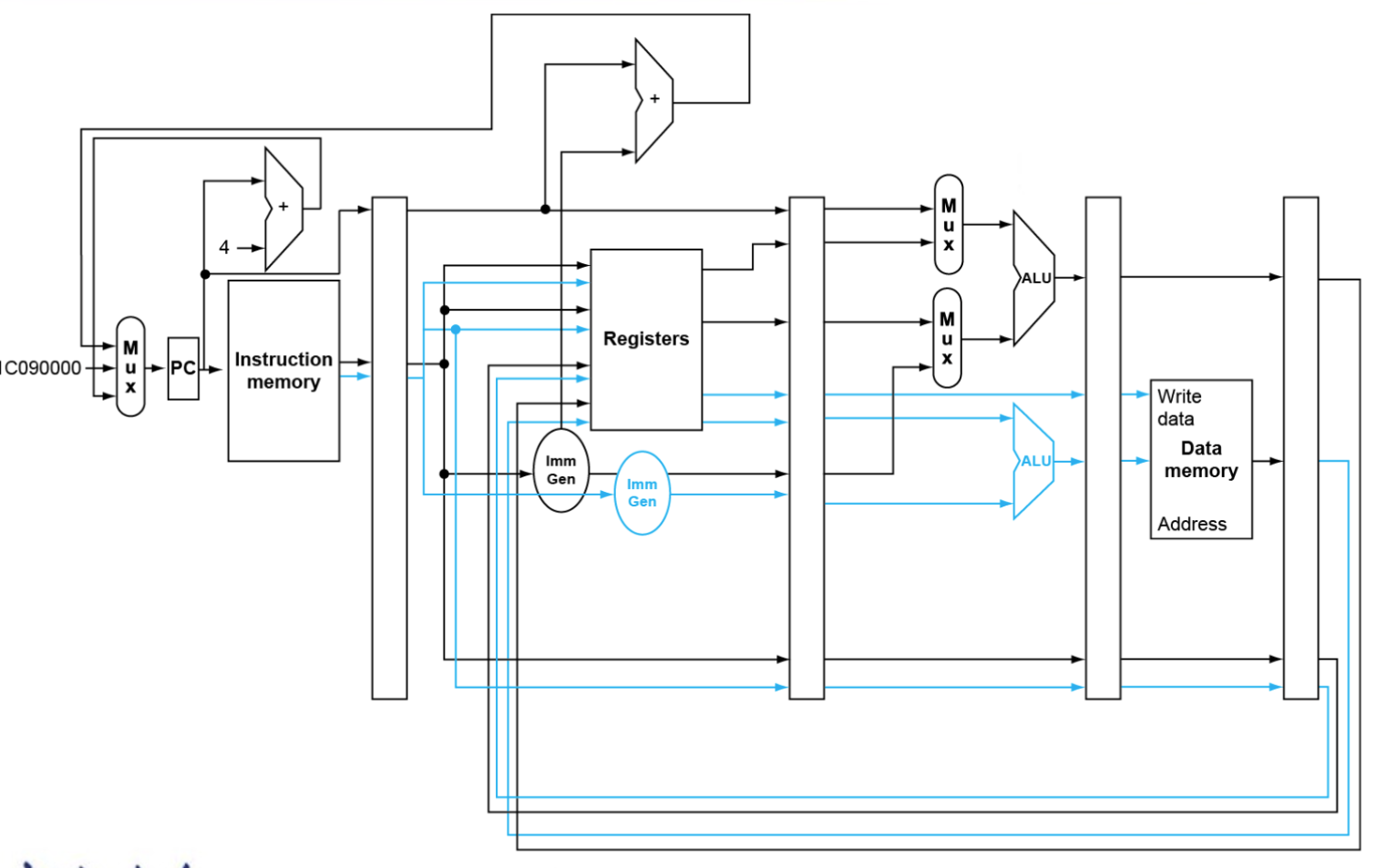
存在问题:遇到依赖差不多废了
例如
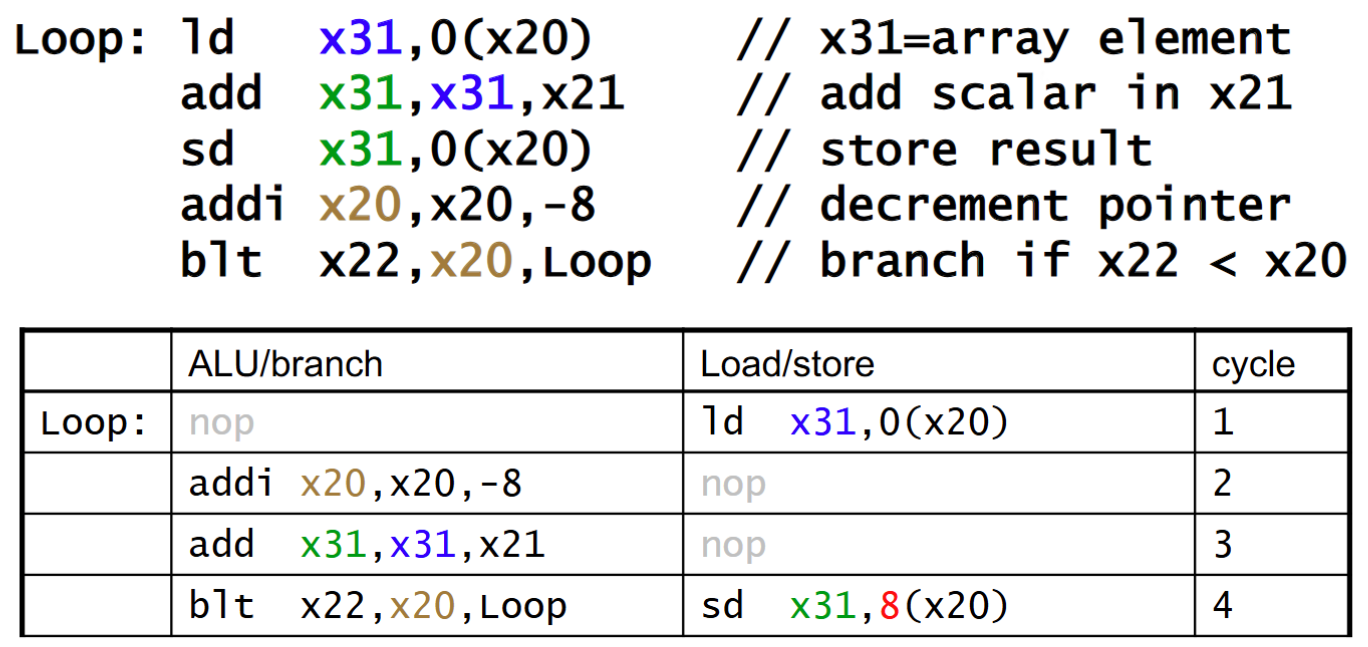
IPC只有1.25
处理方法: Loop Unrolling (编译器实现)
上图的循环可以几次循环捆在一起展开,让并行性提高
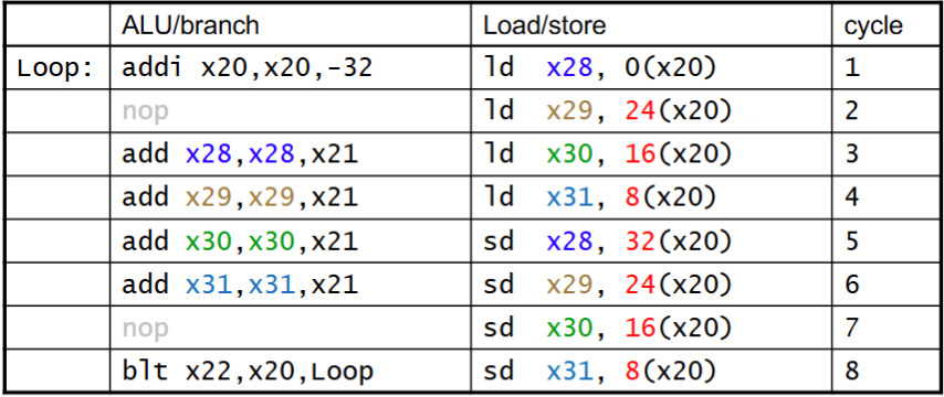
IPC提高到1.75
可以以这个例子理解
for(int i = 0; i < 20; ++i) a[i] += 5;Loop Unrolling后
for(int i = 0; i < 20; i+=4){ a[i]+=5; a[i+1]+=5; a[i+2]+=5; a[i+3]+=5; }a[i]+=5的过程改成RISC-V需要先ld再add再sd,改写后可以先全部ld再全部add再全部sd,冲突化解。
Dynamic Multiple issue
- “Superscalar” processors
- CPU自行决定处理几条指令(在避免hazards的前提下)
- 不需要编译器(虽然编译器可能有用)
- 可以支持乱序执行,结果依然顺序写入寄存器/Memory
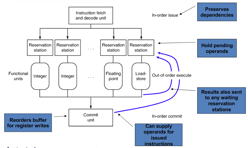
- 原因:编译器不总是理解何时有stall, 对branch结果了解不够实时,不专精于本指令集等
Register Renaming
- 解决指令在流水线中使用相同寄存器导致的冲突
- 如果操作数可用了就从 register file 或者 reorder buffer 放到 reservation station 去
- 否则后续由功能函数 直接提供到 reservation station,不经由寄存器
- 解决指令在流水线中使用相同寄存器导致的冲突
Speculation
- branch : 预测结果并依据预测结果继续算,但是直到 branch 的结果出来再确定计算结果要不要
- Load : 预测地址、Load的值、 bypass处理等。同样等到 speculation 被确认后再 commit
异常与中断
- 不可预测事件(例如溢出、不合法指令等)
- 外部导致的
附 录
RISC-V operands
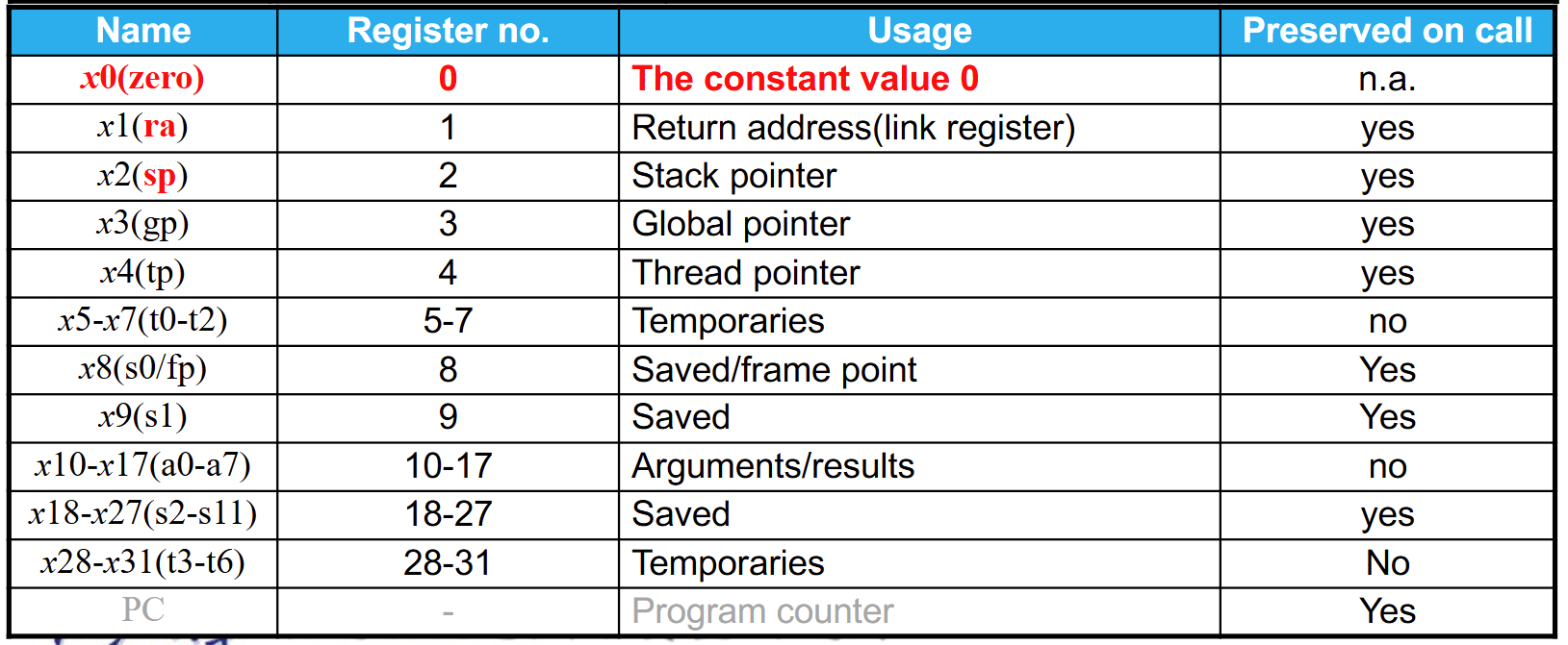
RISC-V assembly language
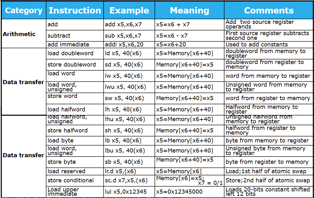
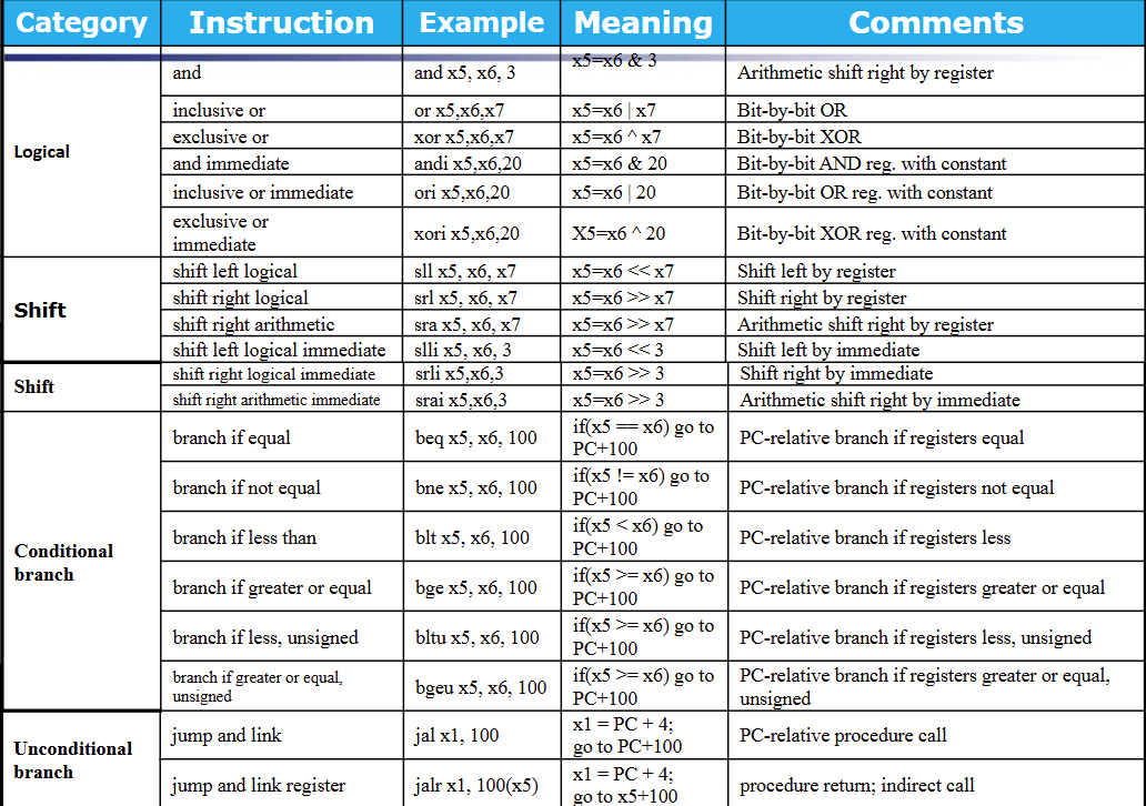
RISC-V instruction structure

RISC-V instruction encoding
